
Operational Amplifier (op-amp)
The operational amplifier (op-amp) is a direct-coupled high gain amplifier to which feedback is added to control its overall response characteristics. It is used to perform a wide variety of linear functions and also some non linear operations. It is often referred to as the basic linear (analog) integrated circuit.
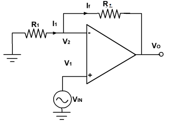
It senses the differences of its two terminals and the output is equal to the product of its amplification factor (A) and the input difference voltage.
Vout = AX(V2-V1)

Pin configuration
- V+: non-inverting input
- V−: inverting input
- Vout: output
- VS+: positive power supply
- VS−: negative power supply
The power supply pins (VS+ and VS−) can be labeled in different ways . Often these pins are left out of the diagram for clarity, and the power configuration is described or assumed from the circuit(Wikipedia).
Properties of Ideal Op-amp
An ideal op-amp is usually considered to have the following properties:
- Infinite open-loop gain G = vout / ‘vin
- Infinite input impedance Rin, and so zero input current
- Zero input offset voltage
- Infinite voltage range available at the output
- Infinite bandwidth with zero phase shift and infinite slew rate
- Zero output impedance Rout
- Zero noise
- Infinite Common-mode rejection ratio (CMRR)
- Infinite Power supply rejection ratio.
These ideals can be summarized by the two “golden rules”:
- I. The output attempts to do whatever is necessary to make the voltage difference between the inputs zero.
- II. The inputs draw no current.
- (source:Wikipedia)